Electronic Design
Assignment: Redraw the Echo Hello-World board, adding a button and LED, and then making it.I started my assignment by using the CadSoft EAGLE Program in order to create my schematic and board. The needed items to complete the schematic were:
microcontroller*
FTDI Header*
20MHz resonator*
10k resistor
Button
Ground
VCC
LED
499 ohm resistor
(given items indicated with *)
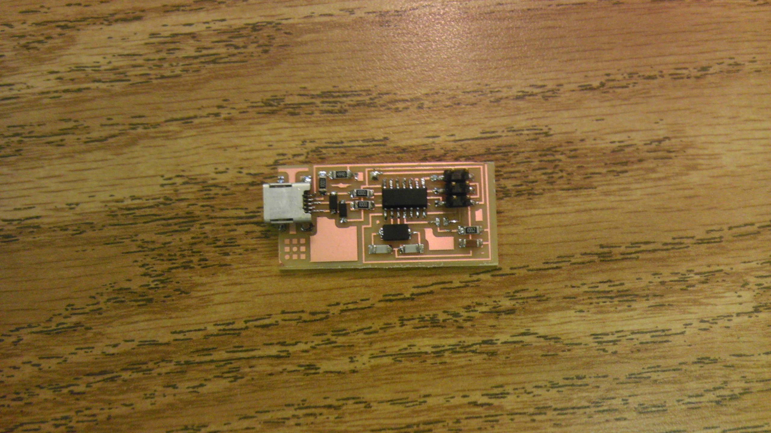
The above picture is my original board that was milled. There were a few issues with this board: namely that traces for my 499 ohm resistor and LED needed to be switched around. Also, our lab was having issues with properly putting the bits inside the Modela and so a bit had been broken in the process (which is why the board looks like it was roughly milled due to a new bit).
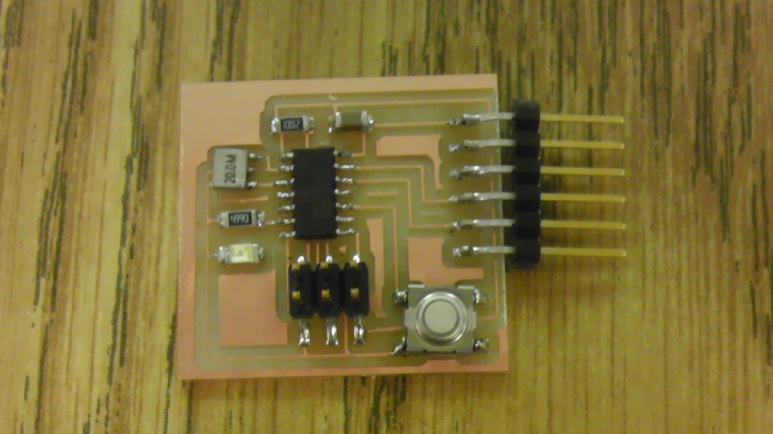
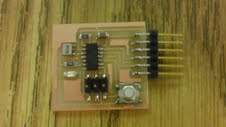
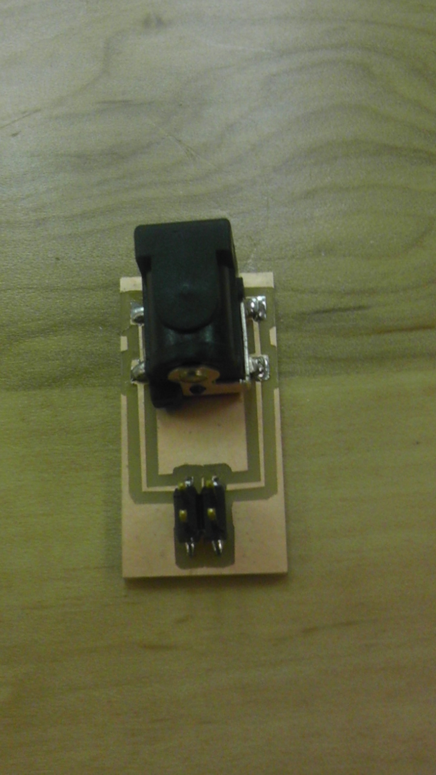
The above image is my end result after successfully milling and soldering my second board.


